OtherMill Initial Documentation
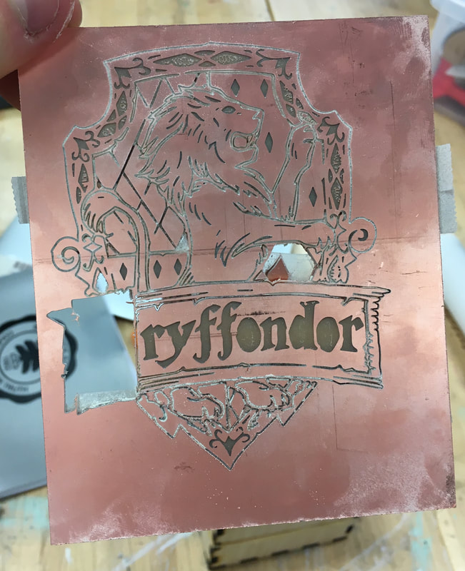
For my OtherMill project, I first downloaded an image off of the internet, and then imported it to illustrator to create a vector map. My initial trace of my image included around 20 different compound paths which were scattered all across my artboard. I had very little individual paths that were not included in with the compound paths. Subsequently, when I uploaded my first design into BantamTools there were many cut lines that I was not expecting to be registered; however, in my lack of experience using the OtherMill, I still uploaded it onto the machine. The resulting milled object turned out to be a disaster, and it started to crumble in my hands from the moment I took it off of the board. Below are pictures of this object.
|
|
I went back into my illustrator file and released all compound paths to see what I was actually working with. I found that not only did I have double vectors, but I also had stroke lines around each fill. After I got rid of these paths and loaded it onto Bantam, it still didn't work, so at the moment I am trying to figure out why my fills are being registered as strokes.
Final OtherMill and Circuit Documantion

|
|
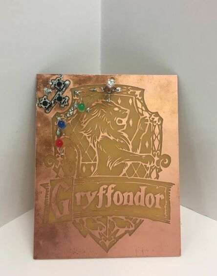
Above, I have two pictures that illustrate the beginning and end stages of my project. On the left, I have the original .jpg file I downloaded off the internet, and on the right is my finished mill with my integrated RGB circuit. As you can probably tell, it didn't come out as pretty as I would've hoped; however, I am happy with my overall product despite some soldering problems. Below I have a couple of images that help to document my process.
|
|
|
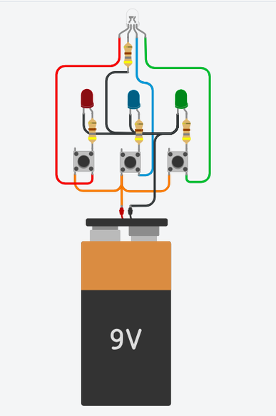
Left: This is a screenshot taken on Tinkercad of the circuit which I incorporated into my milled object. The circuit is made up of one 9V battery, four 480Ω resistors, three switches, three single color LED's, and one RGB LED. When one of the switches is pressed, the LED attached to that switch is supposed to light up, and simultaneously the RGB LED should light up in the same color as the single color LED.
|
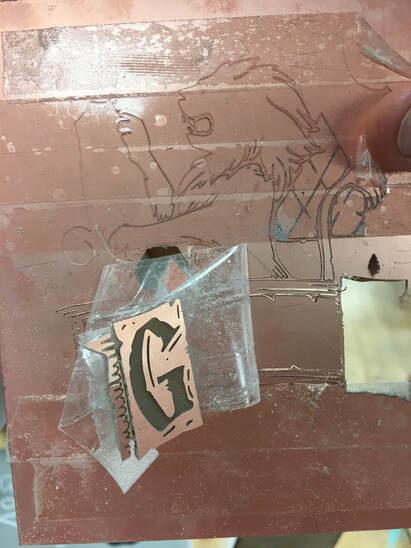
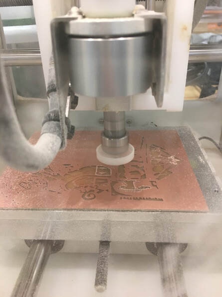
Right: This picture was taken half way through the engraving part of my final mill. The entire mill took over an hour to complete due to the intricacy of the design. Furthermore, on the left side of the spoilboard, you can vaguely make out my solder holes which I chose to drill before I started engraving.
|
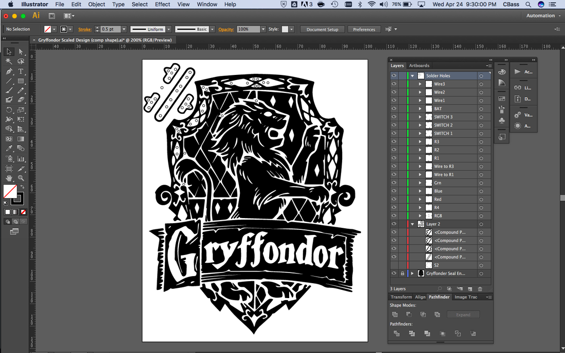
Left: This screenshot was taken from my final illustrator file which includes all of my engravings and solder holes. You can clearly make out the makeshift pads I designed in the top left of the file which act as the positive rail of my circuit. The rest of the white space (unless they are closed shapes) are connected to ground.
|
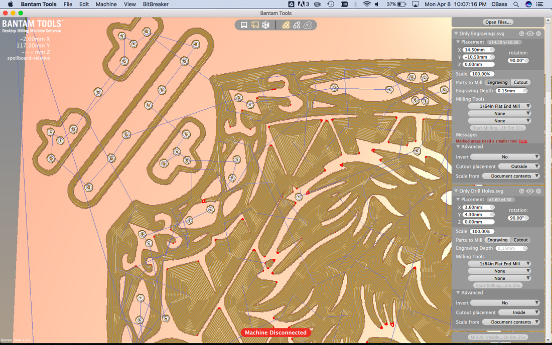
Right: This is a screenshot from BantamTools and represents how the Othermill interprets the illustrator file. For example, the paths that contain no fill but have a stroke weight (all the solder holes) look like white holes meaning that it is a cutout. On the contrary, all the paths that don't have a stroke but do have a fill become an engraving.
|
