Building a Synthesizer
|
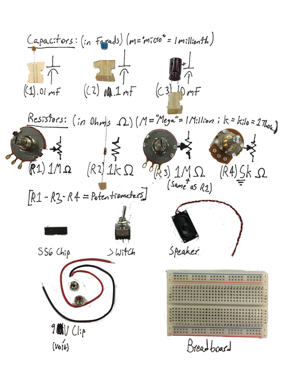
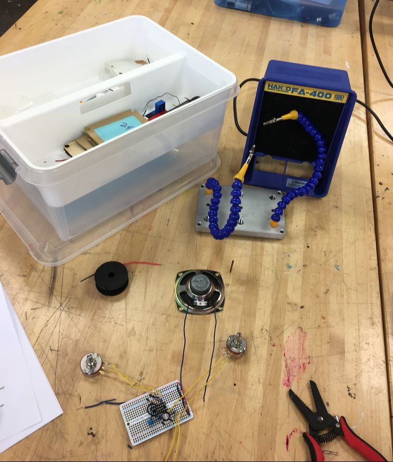
My Components:
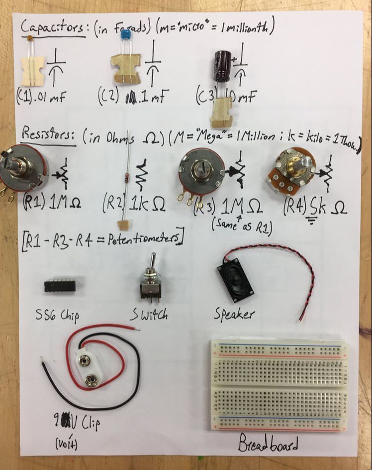
I knew almost all of my components due to past experiences i've had with circuits. The only one I was not familiar with was the 556 Chip. I searched it in my browser, and clicked on the Wikipedia page. I learned that it is an Integrated Circuit Chip that causes delays between the pulses of energy in a circuit, causing there to be a time delay in the circuit. |
Building Process
|
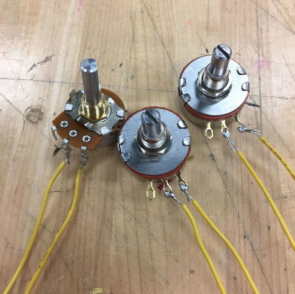
Testing and Soldering:
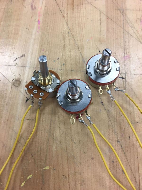
After I gathered and identified all my parts, I proceeded to test the resistance of the three Potentiometers. I needed to find out which direction, if rotated, increased the resistance, and which way decreased the resistance. After I discovered that turning the stem of the potentiometers counterclockwise increased the amount of resistance, I progressed to soldering. Although this was one of my first times ever soldering, the adhesions between my wires and my potentiometers turned out great: there was a small amount of exposed wire and unsoldered metal. 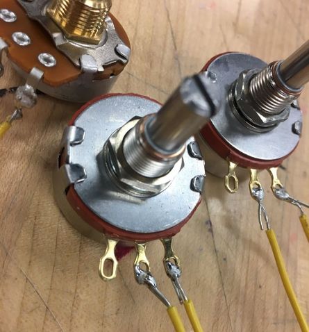
|
|
|
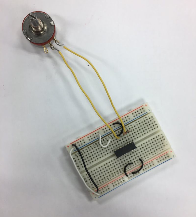
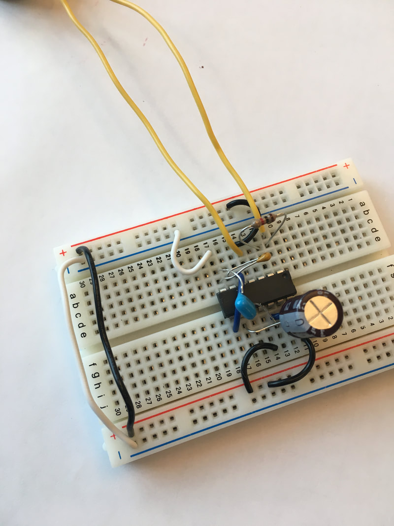
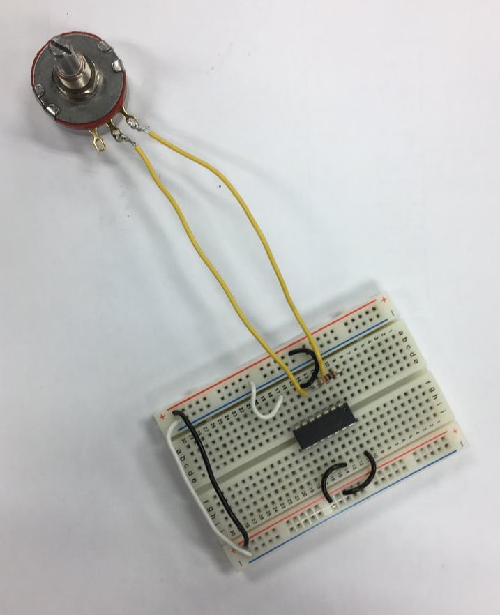
Setting up the Breadboard:
The first step in setting up my breadboard was to put the 556 Timer Chip into my breadboard. I connected my positive and negative sides of my breadboard together thus connecting both sides of the breadboard. I then added the R1 (potentiometer) and R2 resistors to my circuit. After placing connector wires into my breadboard, I was ready to move onto the next stage of putting in my capacitors. |
|
|
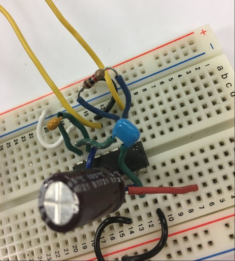
At this point, I started to add my capacitors. I put the .01 and .1 capacitors in first and then proceeded to add my polarized capacitor last. Also, I added two more jumper wires. After placing all of these components in their respective spots on the breadboard, I realized a lot of metal was showing which could lead to a short circuit when I tried to turn it on. So I decided to add some Shrink to the wires of my capacitors and to the R2 resistor (picture to the right).
|
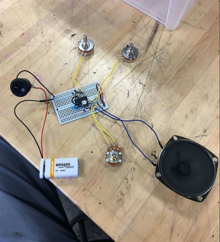
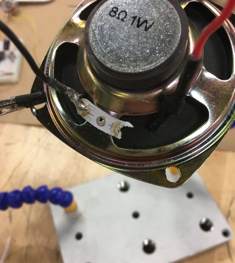
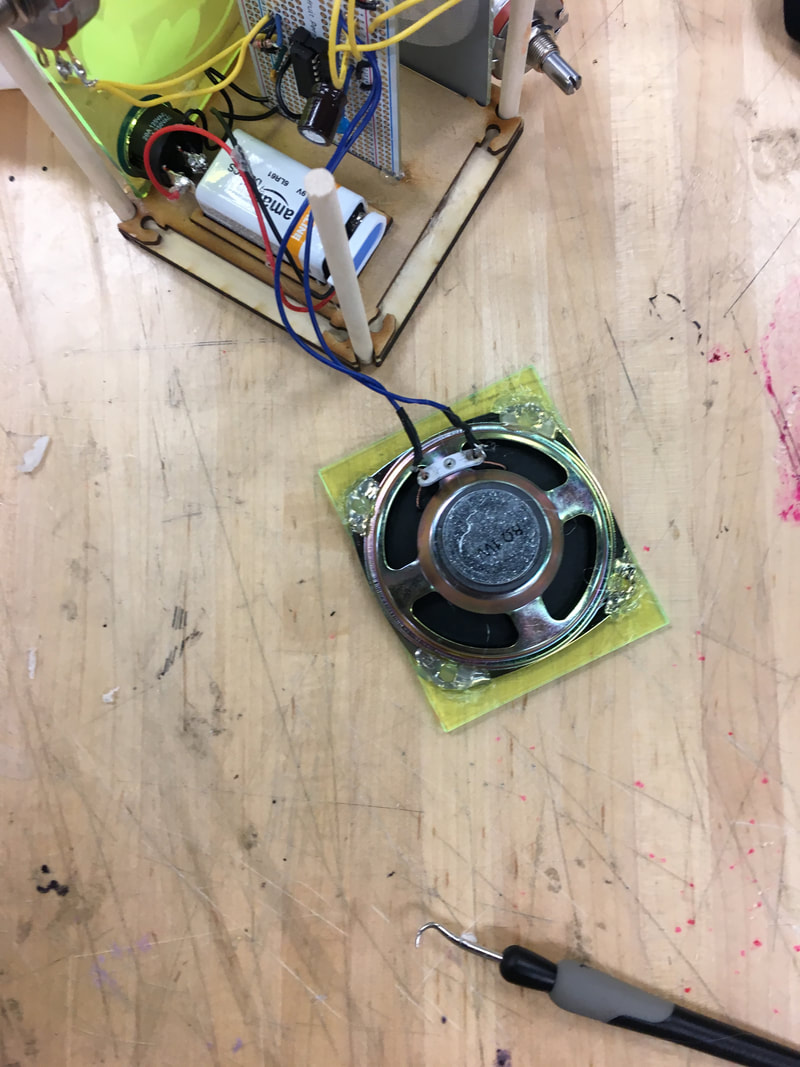
Finally, I added my 9V snap connector, speaker, and remaining potentiometers to my circuit (not pictured).
Troubleshooting and Reflection
First Troubleshot:
After assembling my synthesizer, I snapped on my 9V battery and awaited for my speaker to emit the sweet sound of submission. It did no such thing. So I checked each port for continuity, which they all had, and tried effortlessly to turn it on again. It still didn't work. I then tested the voltage of the battery and realized that the voltage of the battery was substantially lower than it was about 15 seconds before. I realized this must be caused by a short circuit somewhere in my circuit. I used the next two classes to continue searching for evidence of a short circuit, but I couldn't find one. At this point, I ran out of time to troubleshoot before Thanksgiving Break.
Second Troubleshot:
After getting back from break I used my first free period to continue troubleshooting. This was very helpful because it helped give me an idea of where I may have messed up my circuiting. Ms. Dixon and I worked on my synthesizer after I assembled the entire breadboard again. We tested each component for continuity once more and then proceeded to exchange parts between my synthesizer and a working synthesizer that Ms. Dixon had made prior, which probably took about 5 minutes for her to do. We tested my speaker; R1, R2, R3, R4 resistors; and my .1 capacitor, all of which worked fine. When we swapped the .01 capacitors, however, the previously working synthesizer was having trouble emitting sound, meaning that this may be the source of the problem in my synthesizer.
Reflection:
This was/is the most challenging project we have done yet this year. I had to apply the knowledge I learned about circuits from the beginning of the year to the actual building process of the synthesizer. I used my newly acclaimed knowledge on soldering, using the multimeter, reading a breadboard, polarity, and general circuitry to help me in the constructing of my synthesizer. Although my synthesizer has not emitted a sound and I am yet to find a definite reason why, I am confident that I will find the source of the problem going forward.
Synthesizer 3D Design Project
|
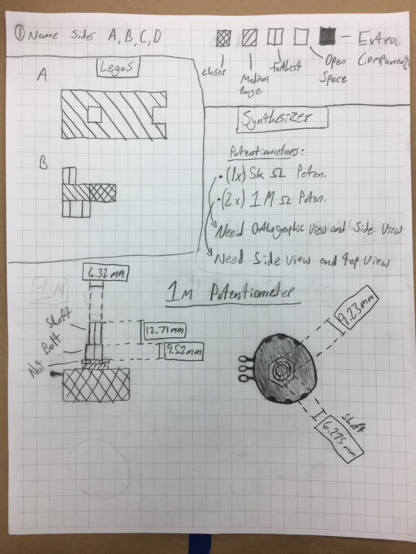
Schematic - 1M Potentiometer
(Side view and Top view) |
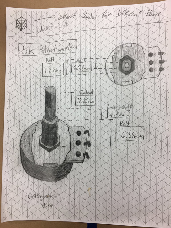
Schematic - 5K Potentiometer
(Orthographic view and Top view) |
|

|
Knob Designs using OpenSCAD (Prototype)

|
|
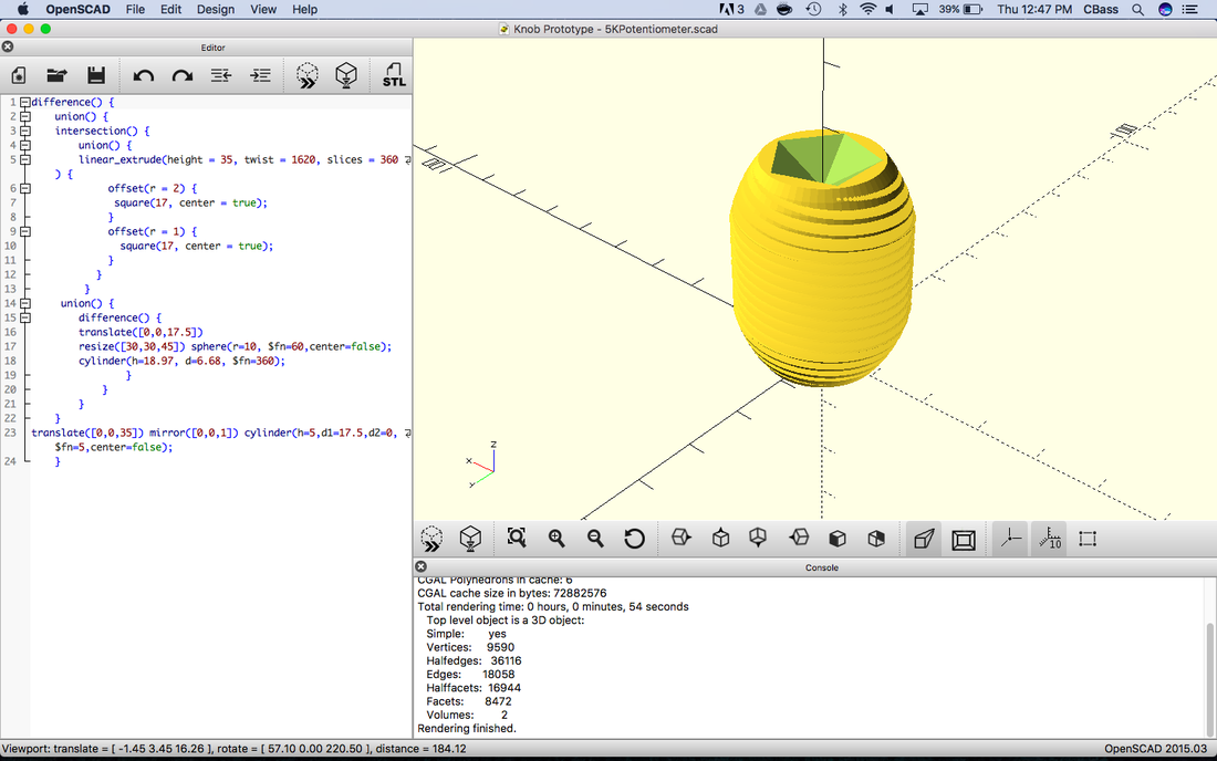
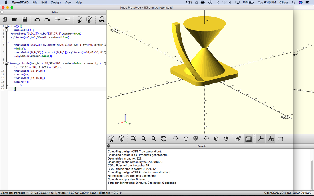
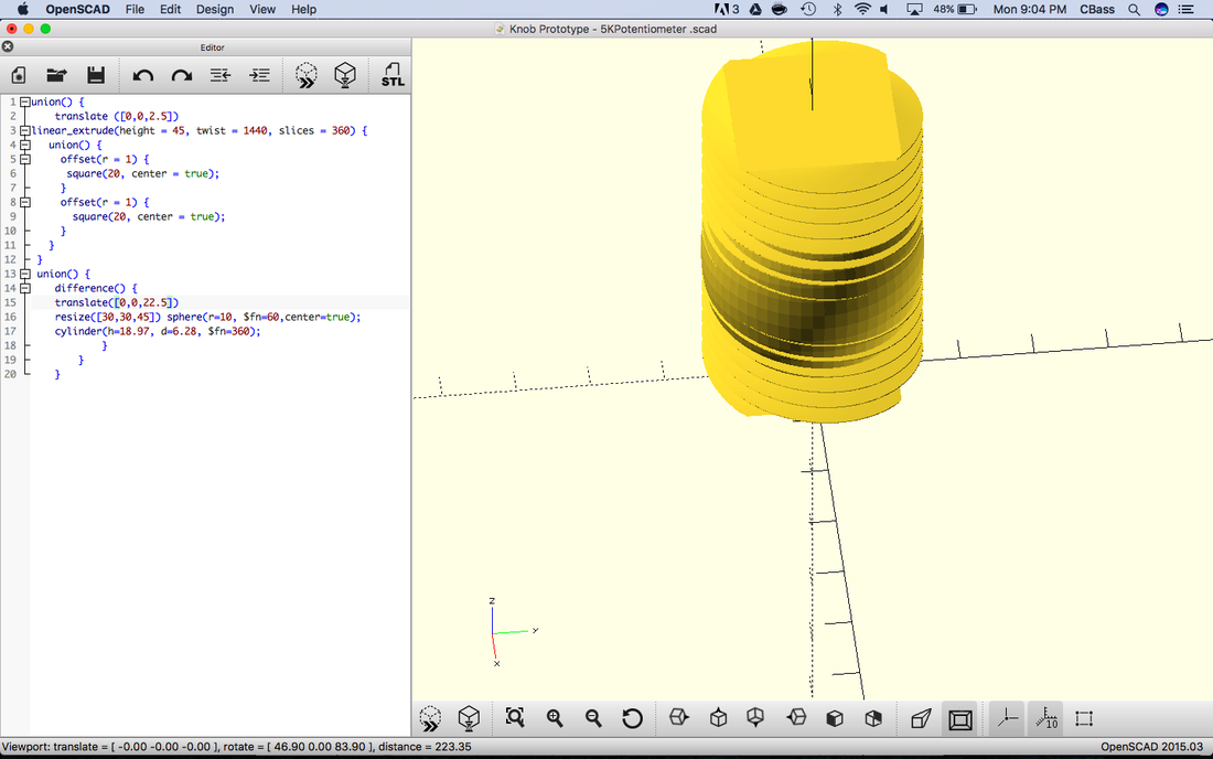
5K Design: Above is my first OpenSCAD design I made for the 5K Potentiometer Knob. At first it was a challenge to learn how to use the code to create the design I was visualizing, but after a few hours time messing with the OpenSCAD wiki, I came up with this. I tried to mimic the grooves on the potentiometer midsection.
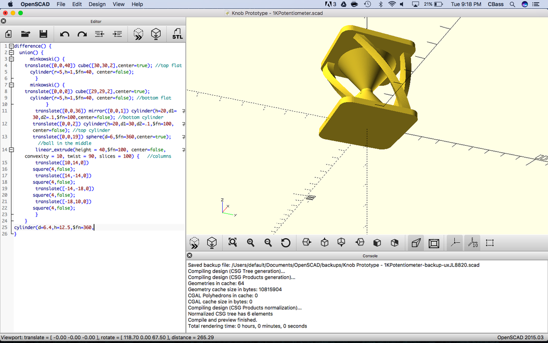
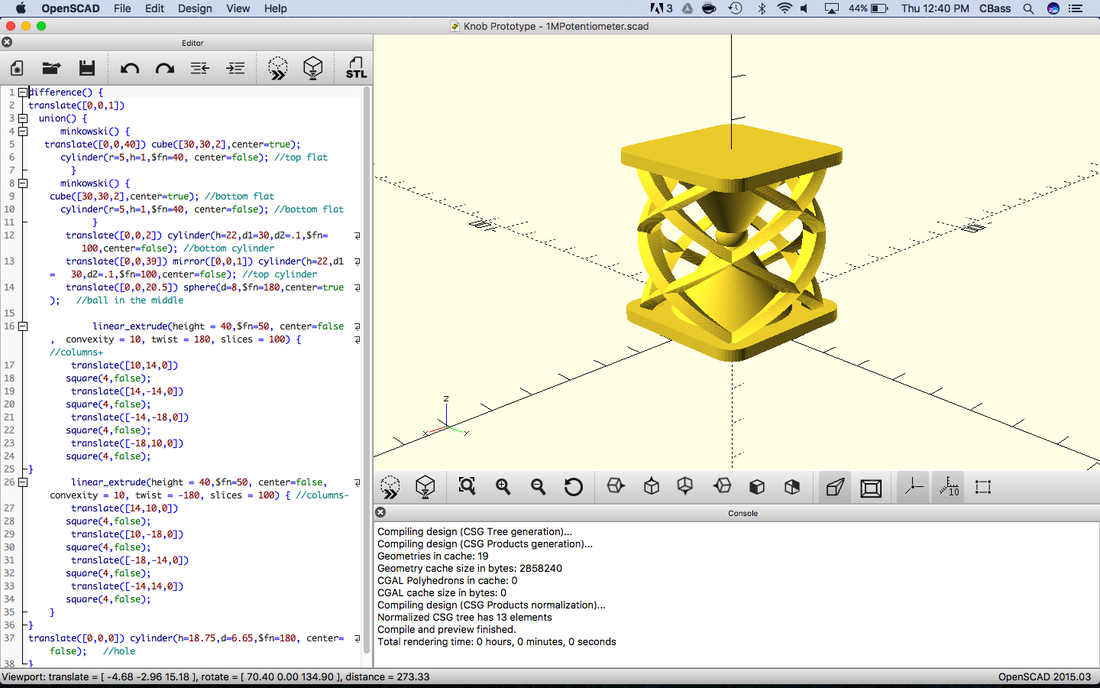
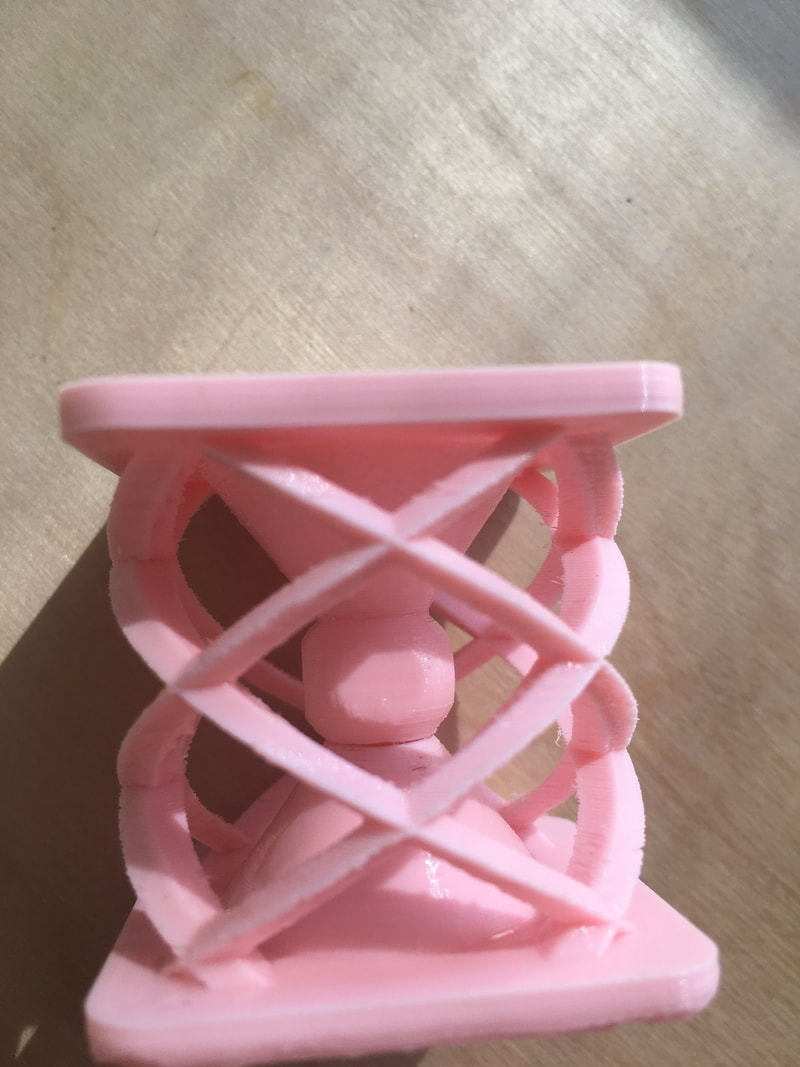
1M Design: Below is my second design for my 1M Potentiometer, taking a much longer time to create than my first design. One of the more funny things is that the middle of my design resembles an hourglass which has no relevance to this project. I think that I subconsciously was thinking about how much time I was spending on my design, so that's why the shape of an hourglass was at the forefront of my mind. Then I was thinking that the skinny middle section of my design might break if not reinforced, so I decided to add columns that twist around my hourglass. There were a couple minor hiccups during the design process, but I got through them and I'm content with my final design.
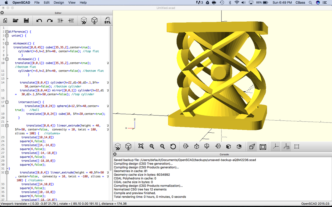
Note: I created a second 1M Potentiometer knob but changed the base to a cylinder instead of a "soft edged" cube.
1M Design: Below is my second design for my 1M Potentiometer, taking a much longer time to create than my first design. One of the more funny things is that the middle of my design resembles an hourglass which has no relevance to this project. I think that I subconsciously was thinking about how much time I was spending on my design, so that's why the shape of an hourglass was at the forefront of my mind. Then I was thinking that the skinny middle section of my design might break if not reinforced, so I decided to add columns that twist around my hourglass. There were a couple minor hiccups during the design process, but I got through them and I'm content with my final design.
Note: I created a second 1M Potentiometer knob but changed the base to a cylinder instead of a "soft edged" cube.
|
|
|
|
Synthesizer Simulation using TinkerCad
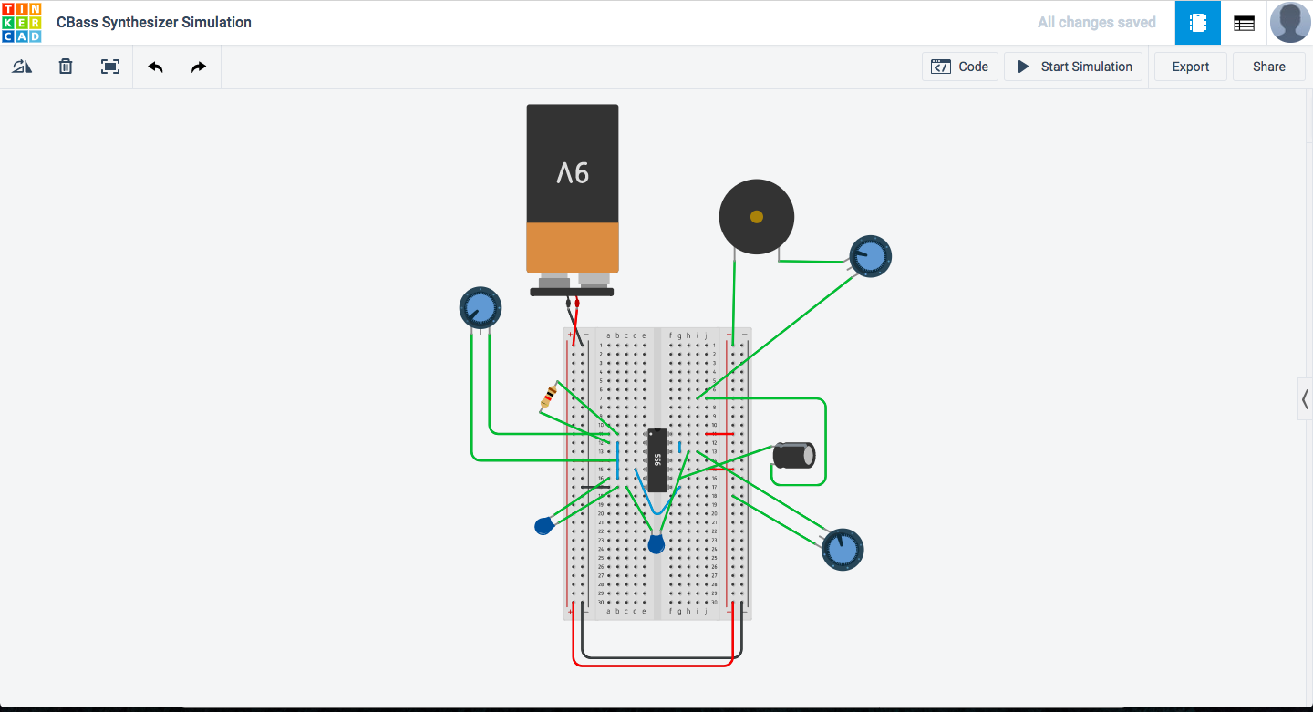
The process of virtually recreating my synthesizer using TinkerCad was both satisfying and challenging, even though I physically created my own a couple months prior. Due to the fact that I never got my real synthesizer to work, it was quite satisfying to get this version to start buzzing when I started the simulation. Problems that arose while building my real synthesizer such as soldering, faulty wiring, and short circuiting, were not present while virtually building my synthesizer. This lessened the amount of time I devoted to troubleshooting. Nevertheless, I still had to spend time troubleshooting my circuit, most of which I devoted to making sure I had the right variables put into my resistors and capacitors. The net amount of time it took me to get my simulation to work was much less compared to my real synthesizer, however roughly the same difficulty.
Link to Simulation: https://www.tinkercad.com/things/dq2A2mmwhXQ-cbass-synthesizer-simulation/editel?sharecode=EVVizdI0HmKLZIxkcq8i4G4S7BOf4YDXorJ6Tb23_sk=
3D Printing Knobs
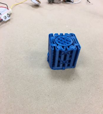
My 3D printing process took much longer than the majority of the rest of the class due to imperfections in my code and coding within the printers. It took me approximately 8 prints in total to get all my knobs done.
|
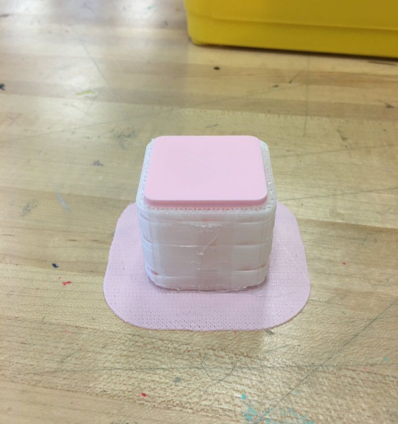
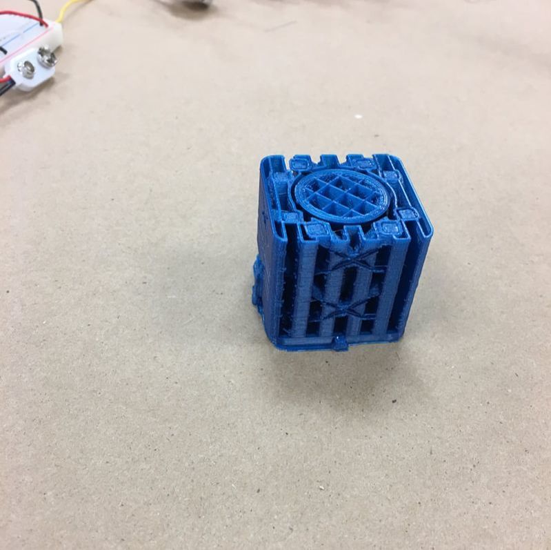
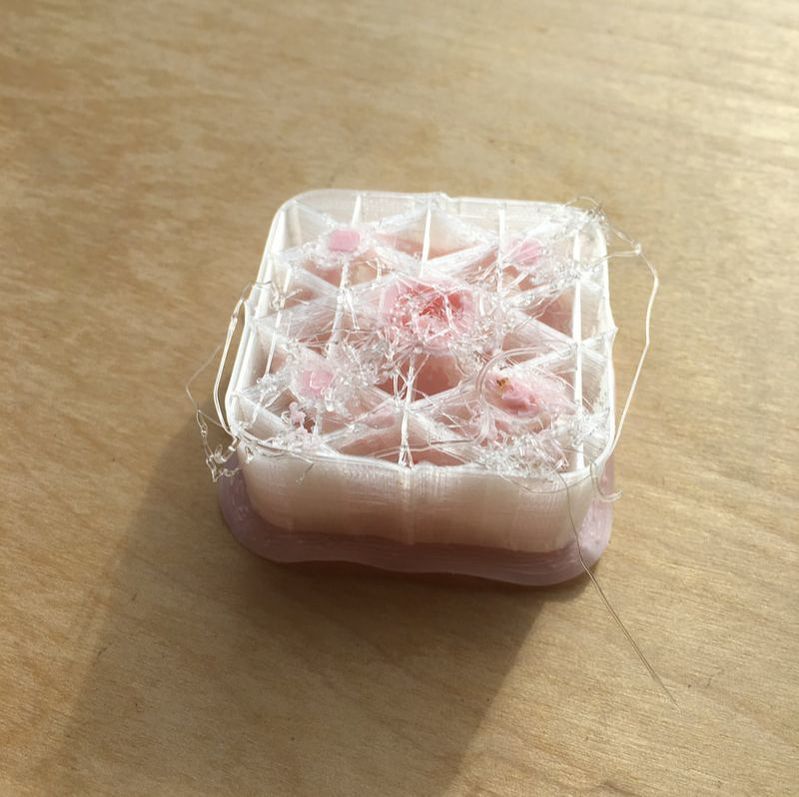
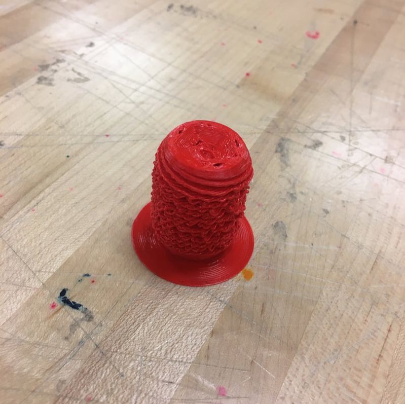
To the right is one of my first prints using the single nozzle printer. As you can see, my design is not only cut off at the top, but also covered completely in plastic supports. I tried for the next day to get as much off as I could, but in the end I gave up and decided to use the dual extrusion printer with the help of Ms. Dixon for the remainder of my prints.
|
|
|
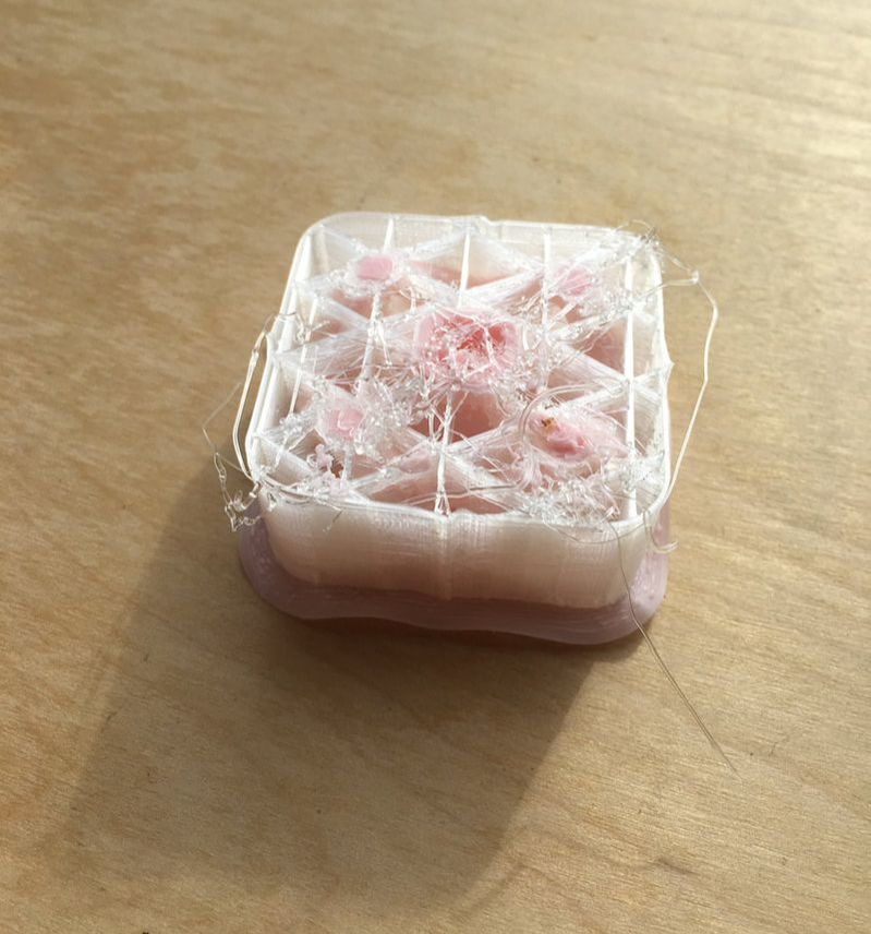
This is my first dual extrusion print, which was going perfectly until the printer decided to stop. I started the printer once again with the same design as before. Unfortunately, this was on Friday, so I was unable to see the end result the next day. Nevertheless, over that weekend I was on a bunch of college visits and I decided to test the effects of hot vs. cold water when dissolving the supports. The hot water dissolved the supports much faster than the supports in cold water (about 3x faster) . Interesting!
|
|
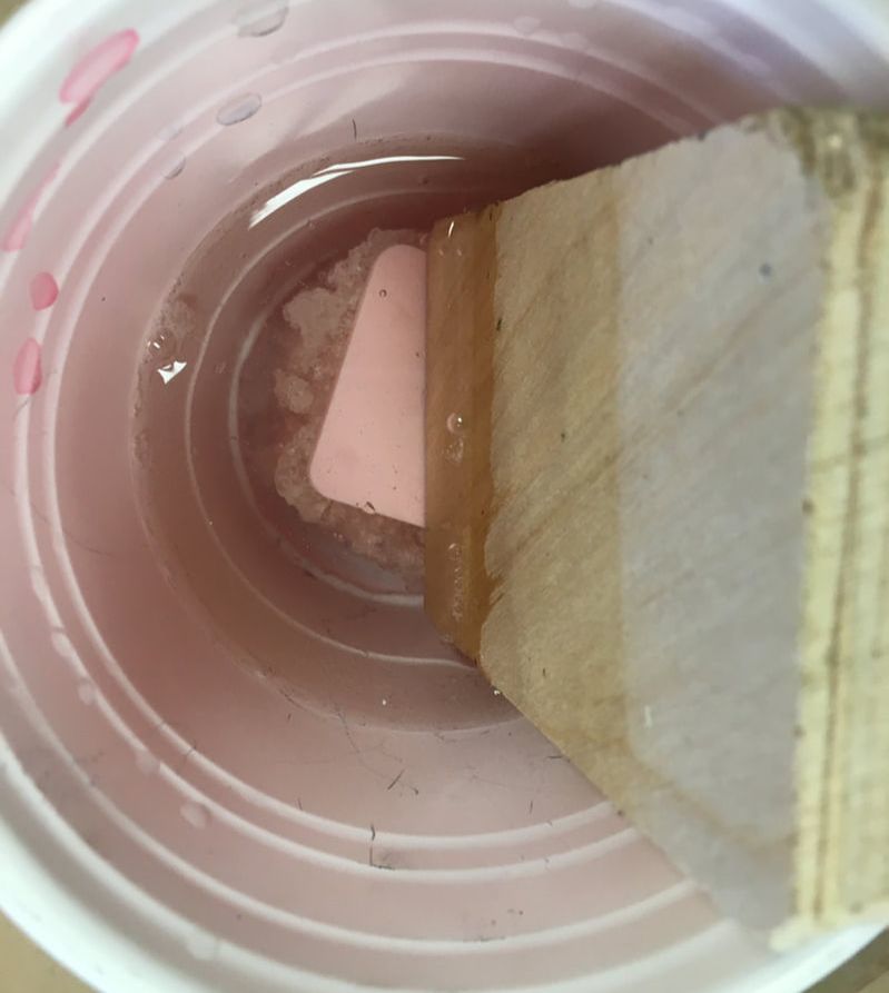
Came back from the weekend to see this beauty sitting in the finished print box. I put it straight into water and let it begin dissolving. I realized that it wasn't fully submerged so I got a wood block from the scrap pile and used it to weigh down the knob. I left this submerged overnight in the lab.
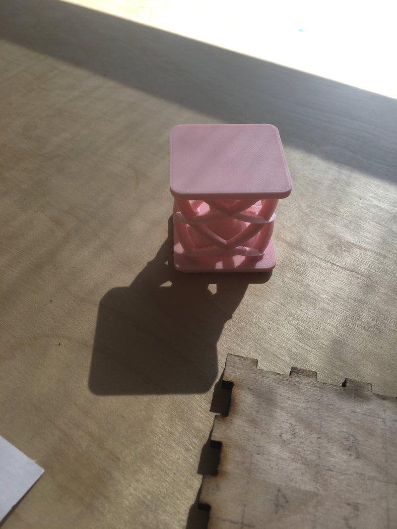
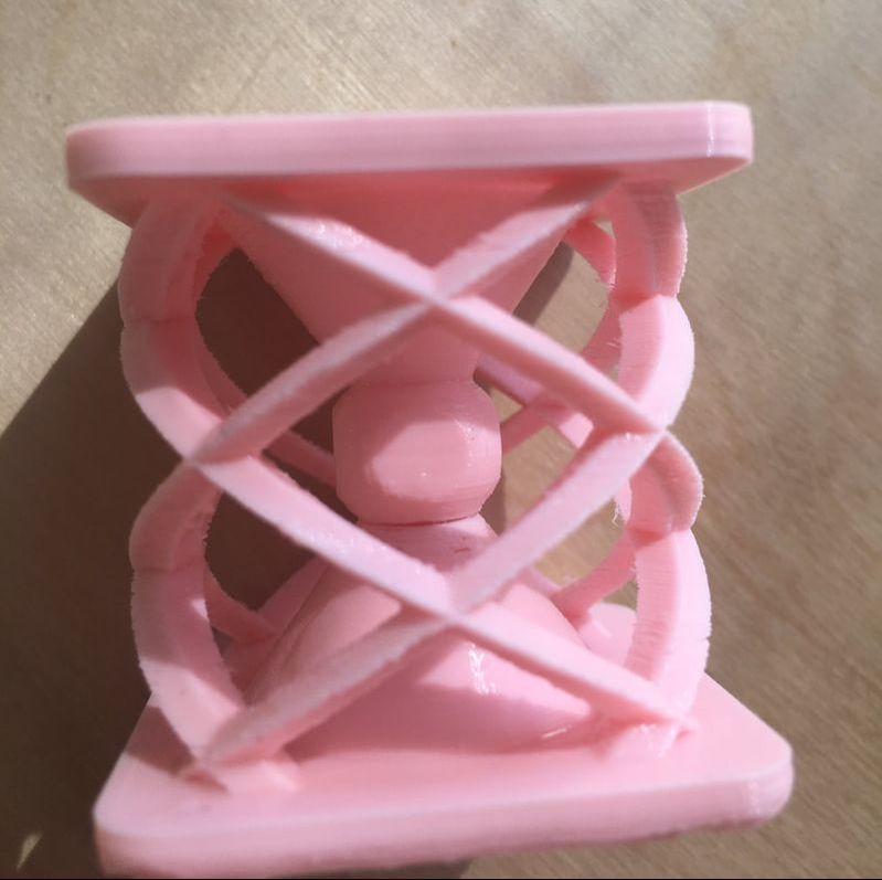
The picture to the right is the finished product of one of my 1M knobs. After printing this knob, the next two were easier to print due to experience and because 5K knob didn't require the dual extrusion printer.
Even though the print looks great, I still noticed a couple flaws in the print. For instance the cone on the bottom isn't even attached to the ball/cube in the center by about a 1 mm. I'm actually shocked that this happened because I would expect the printer to mess up when it got to that point.
Looking back, the same problem must have occured in my first dual extrusion print causing it to stop short. |
|
Acrylic and Mirror Designs
I started this design process back before break, during the storm, in a starbucks because my house was without power. In the end, I actually got rid of everything I created on that day besides from the three potentiometer holes. The majority of my design process took place in the last week of break and the first week we got back. I decided to go with a superhero theme - for some reason.

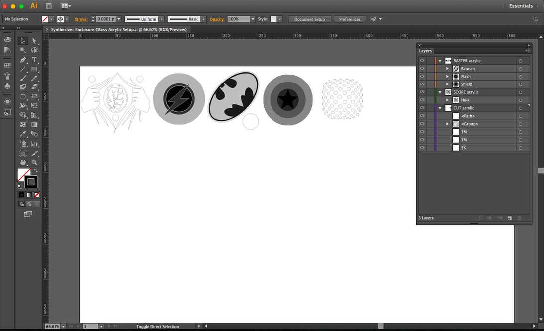
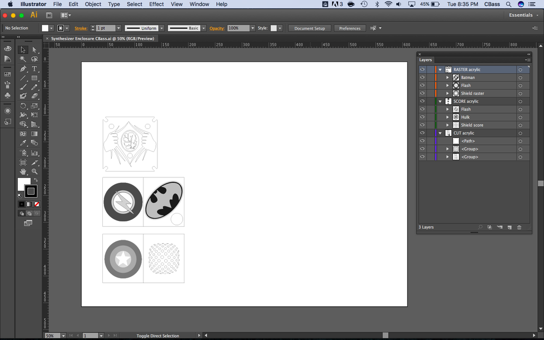
Screenshot from Illustrator
|
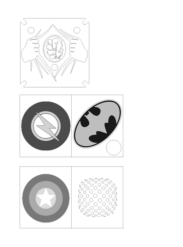
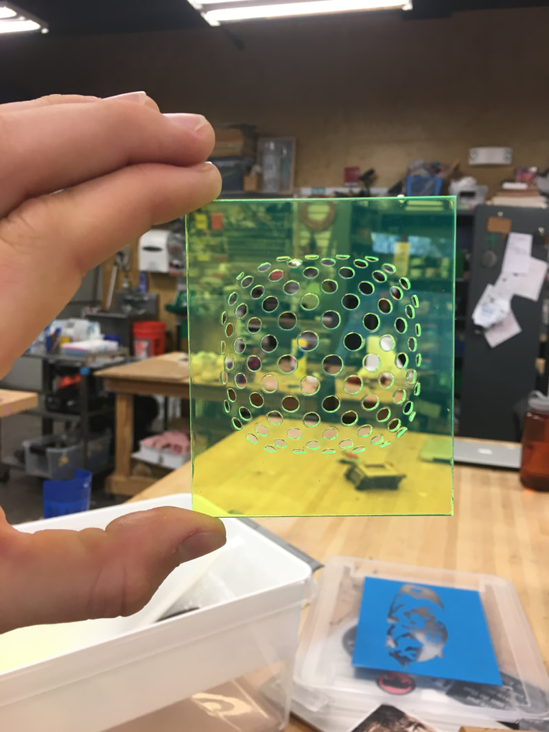
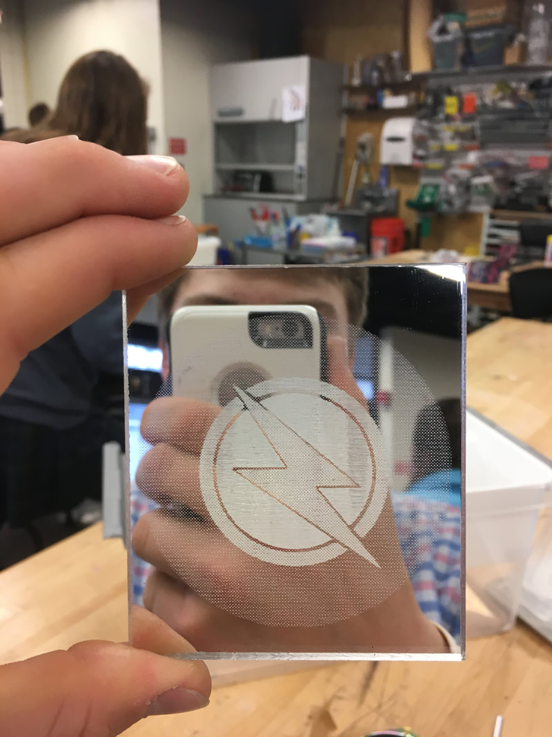
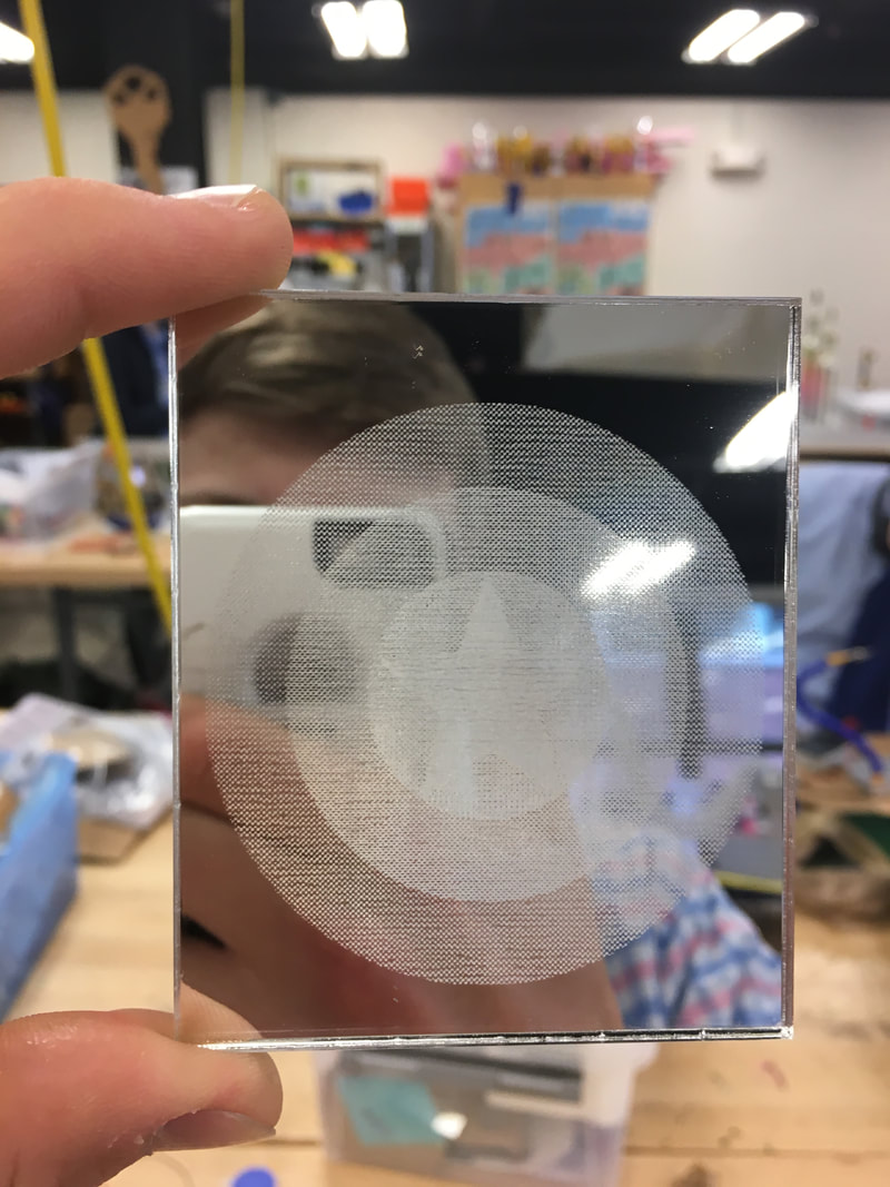
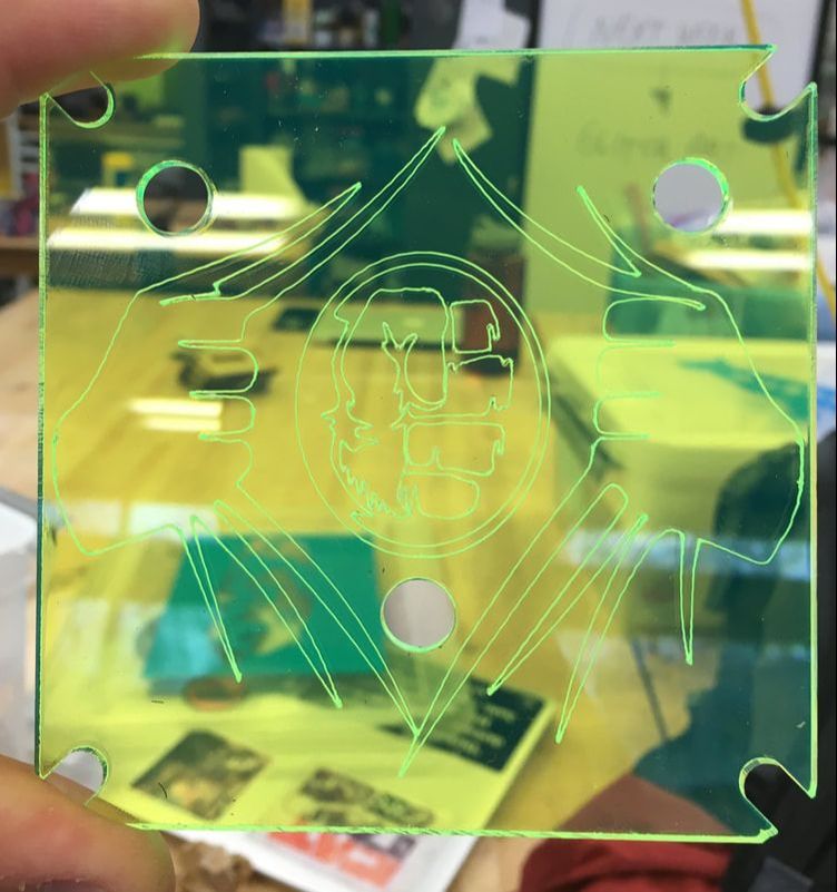
First, I designed Captain America's shield using the circle and star tool in Illustrator thus avoiding having to trace it from a .jpg image (and because I personally like vectors more than bitmaps). After Cap's shield, I downloaded three other logo images: the Flash, Batman, and the Hulk behind a torn shirt. After I traced the images and got rid of any double/excess vectors, I designed the holes for the speaker. For this process I took the dimensions of the speaker and created a circle. Then I did a series of other things: Selecting the texture "dots" within swatch libraries, I used the live paint bucket to fill the circle in with dots that were evenly spaced and sized. Then I rasterized the circle, traced, expanded, and used the fisheye warp to give it a cool bubble type look.
|
|
|
This is my artboard rearranged to fit the dimensions of the laser cutter. In order to print my raster design on the mirror, I had to flip the design vertical and invert the colors. Also, I had to flip my score layer (the hulk one) vertical in order to retain the exact design.
|
|
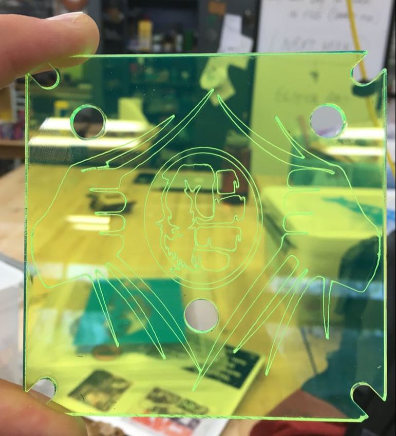
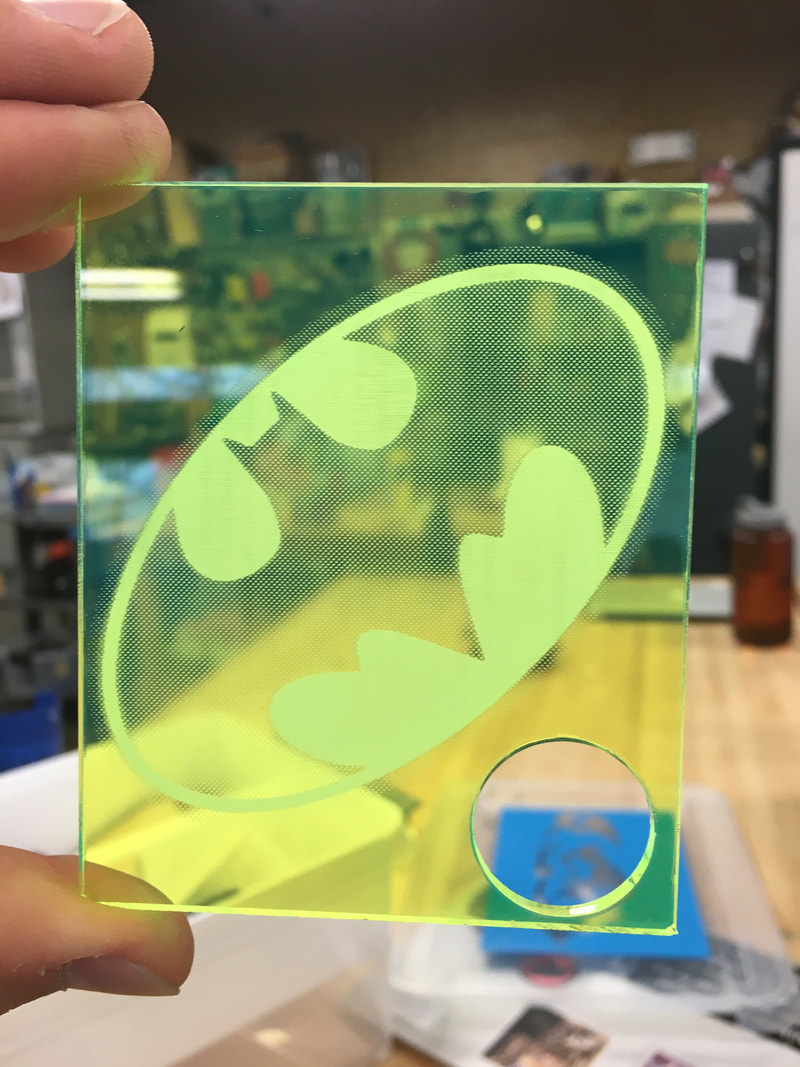
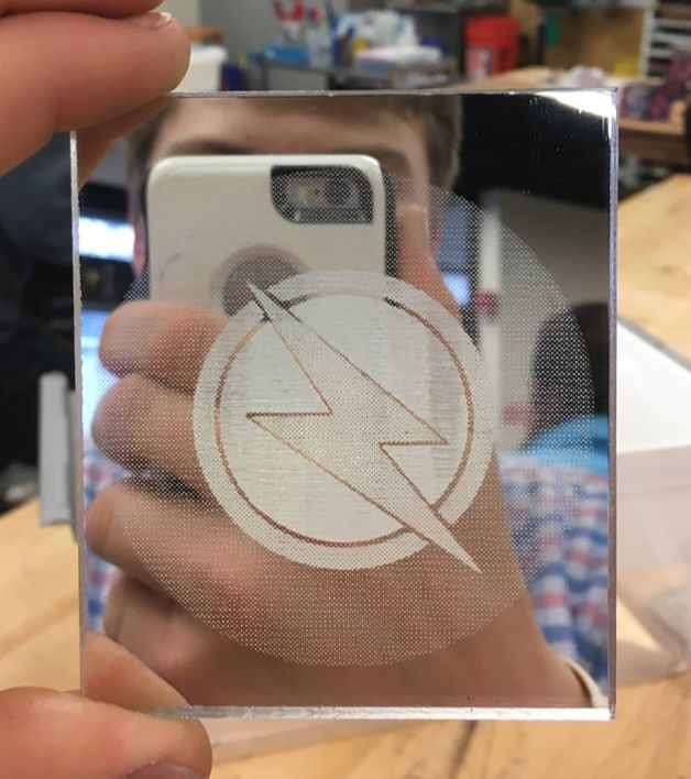
Final Cuts/Rasters/Scores:
| img_28172.mov |
| img_2819_v2.mov |
Final Reflection
11/10/17
11/17/17
|
11/17/17
1/23/18
|
1/30/18
2/7/18
2/12/18
2/20/18
3/6/18
3/29/18
4/4/18
4/4/18
|

1/31/18
2/9/18
2/14/18
2/28/18
3/25/18
3/29/18
4/4/18
4/4/18
|
Learning/Challenges:
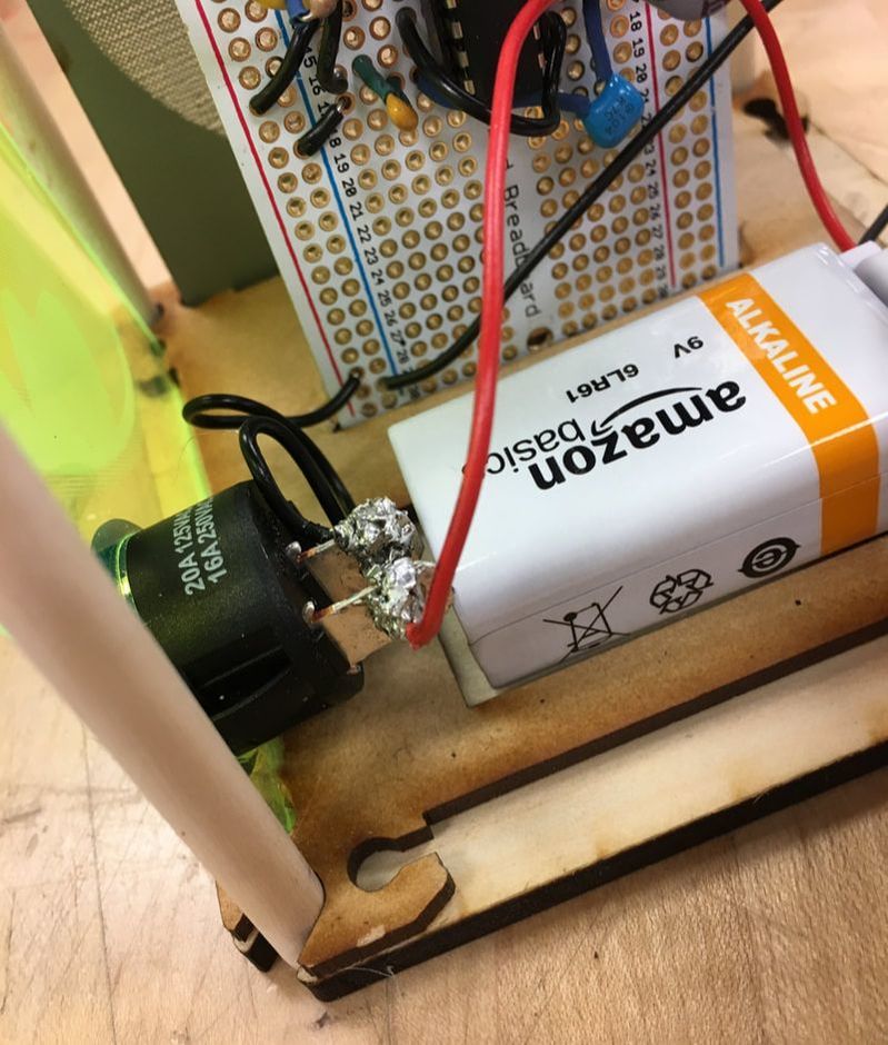
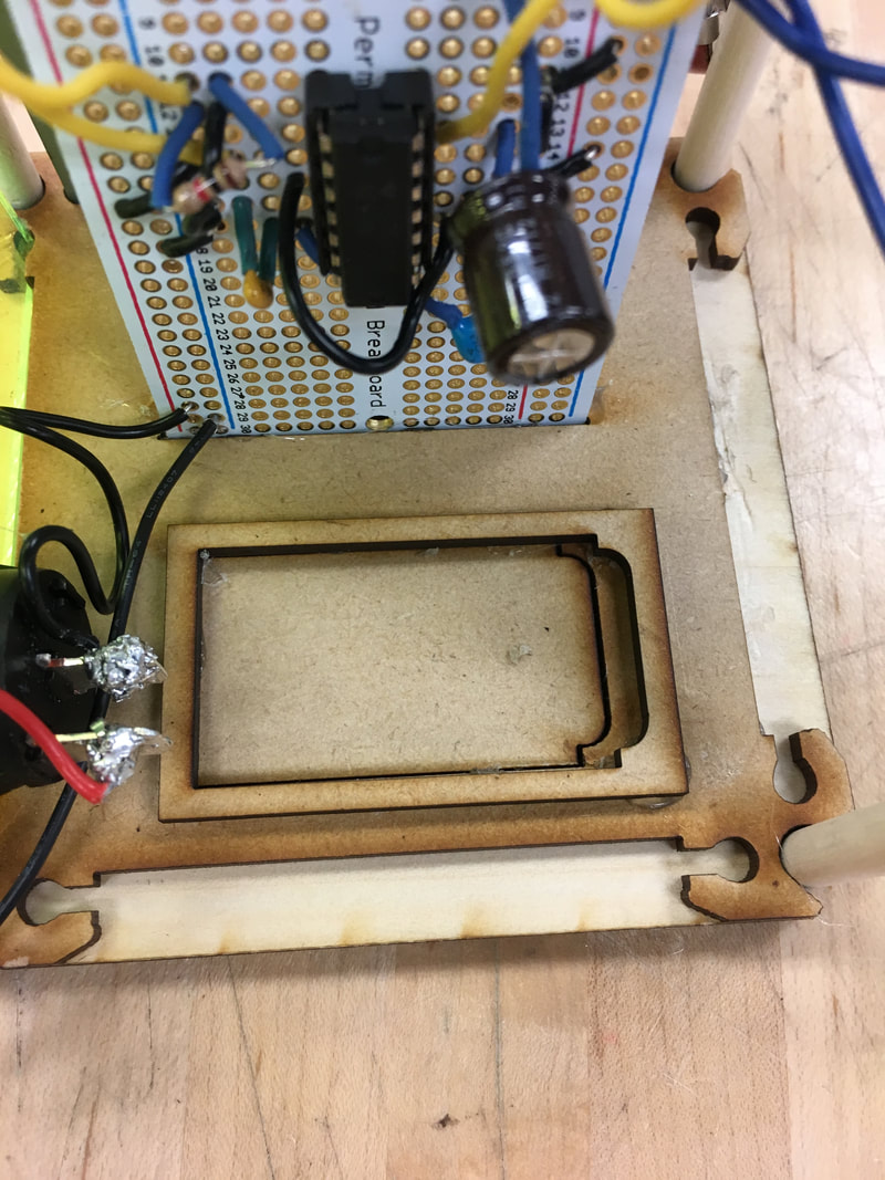
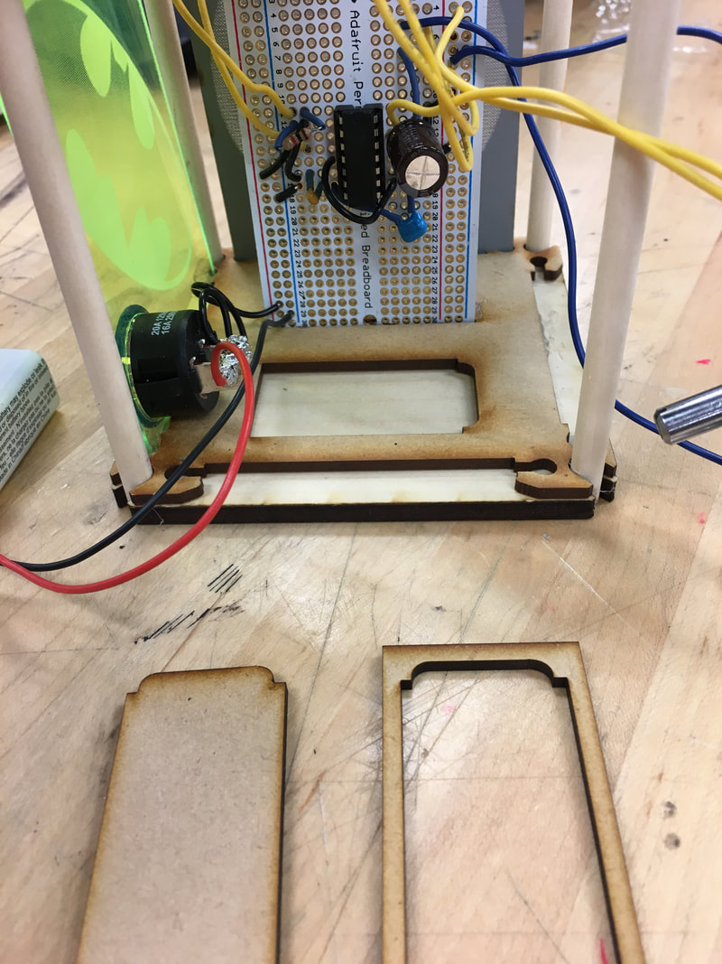
Above are pictures that highlight my entire Synthesizer Project. From finding the voltage, resistance, and polarity of my simple components to assembling my enclosure, I encountered a wide variety of challenges. For example, I occasionally would use too much solder on my perboard causing some of the solder to touch other rows in the circuit. This led to multiple short circuits and a lot of extra time spent on desoldering my wires. Furthermore, because my OpenSCAD designs were relatively intricut, the printers often failed to print due to excess commands lost within my lengthy code. More recently, when I was assembling my enclosure I noticed my battery couldn't fit in the original socket because my switch was in the way. So instead of modifying my switch, I decided to modify the socket. I printed another socket to plug the hole along with the outline of socket, which I could move away from the switch. In the end this seemed to work well.
Looking Ahead:
Although I'm not done assembling my enclosure, I think I can confidently say the hardest/most fiddly part of this project was soldering all the wires to the purfboard. In the future I'm going to be more disciplined about the amount of solder I use on each wire. Also, I should spend a little more time planning my enclosure before I attempt to assemble it. Besides soldering, minor circuitry difficulties, and my messy hot glue skills, this project was successful and enjoyable.
